

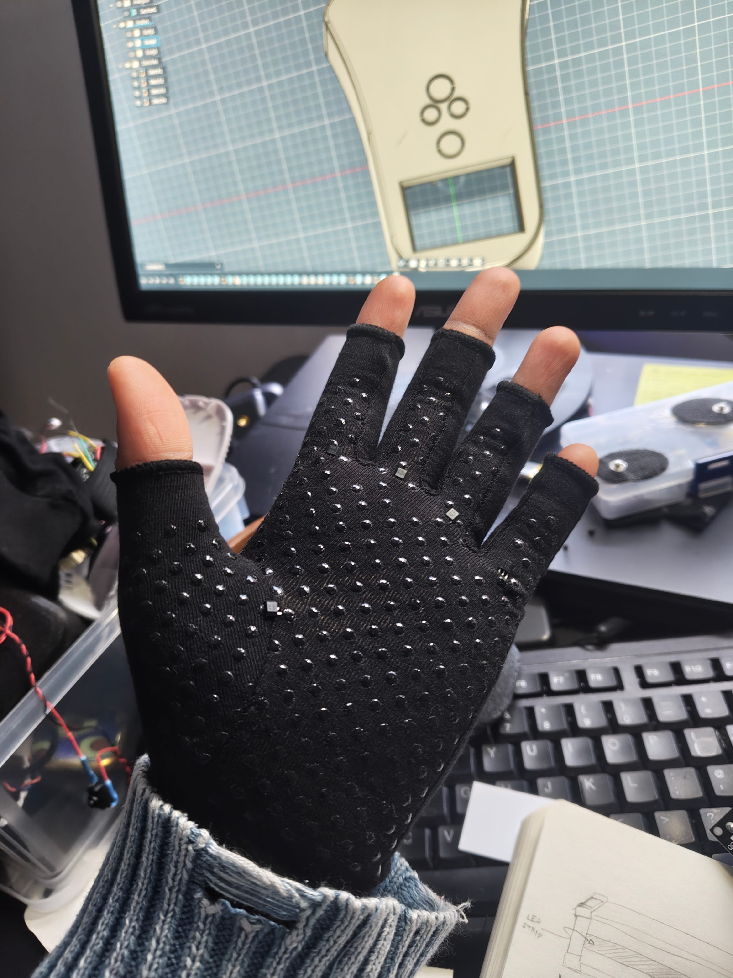
GROUND TRUTH GLOVE (using Hall Effect sensors)
Track fingers with hall effect sensors!
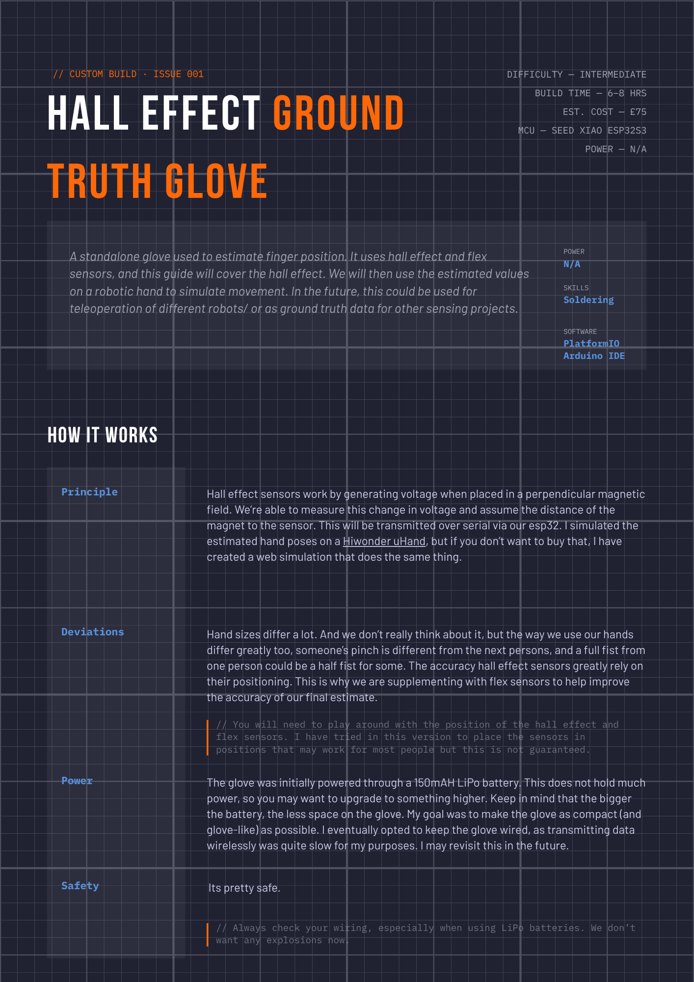
About
I created these to collect data for my sEMG wristband. This will be used in the machine learning process as ground truth for the band. It can also be used to control a Hiwonder uHand, and I will be posting a tutorial for that next.
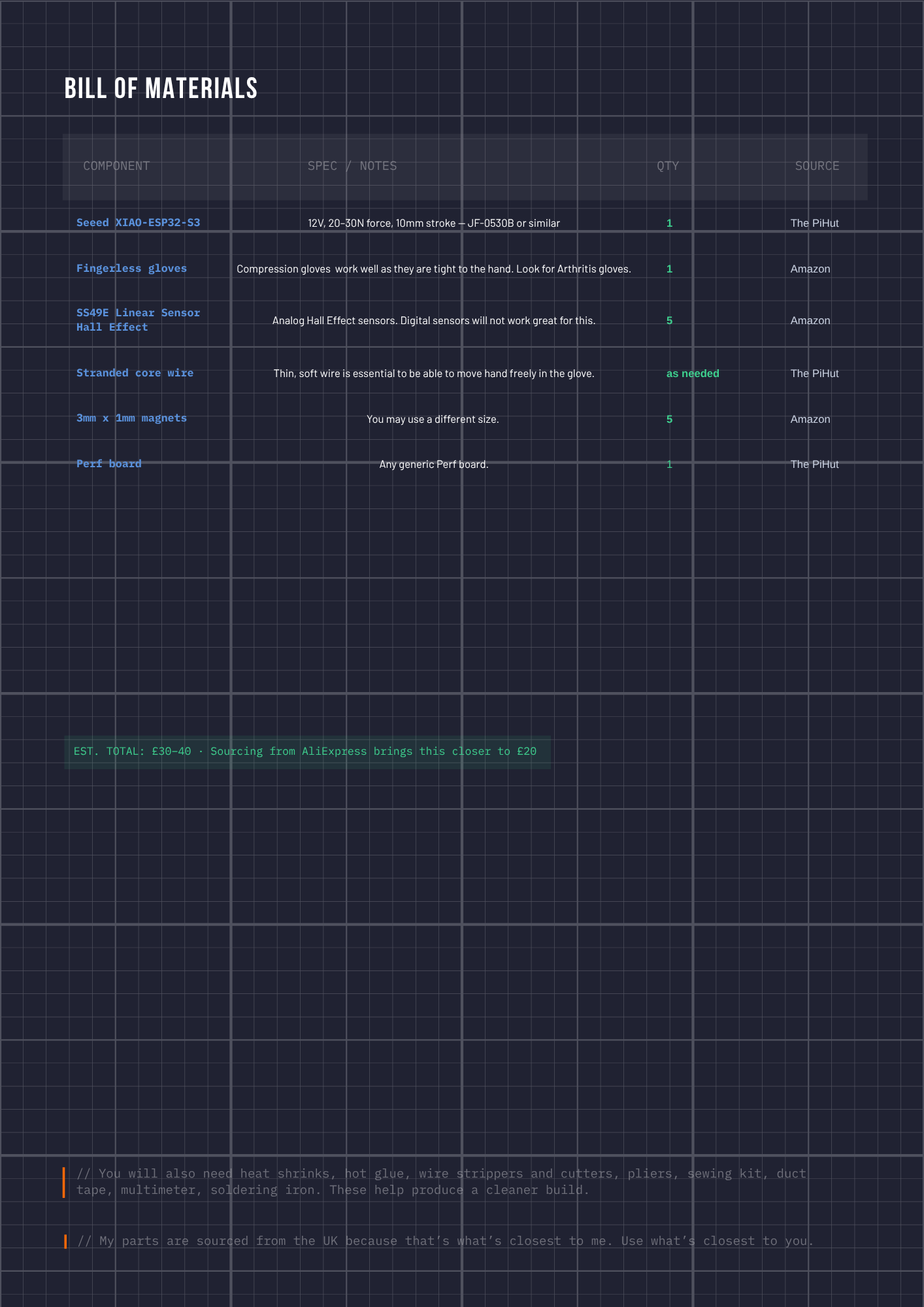
BOM
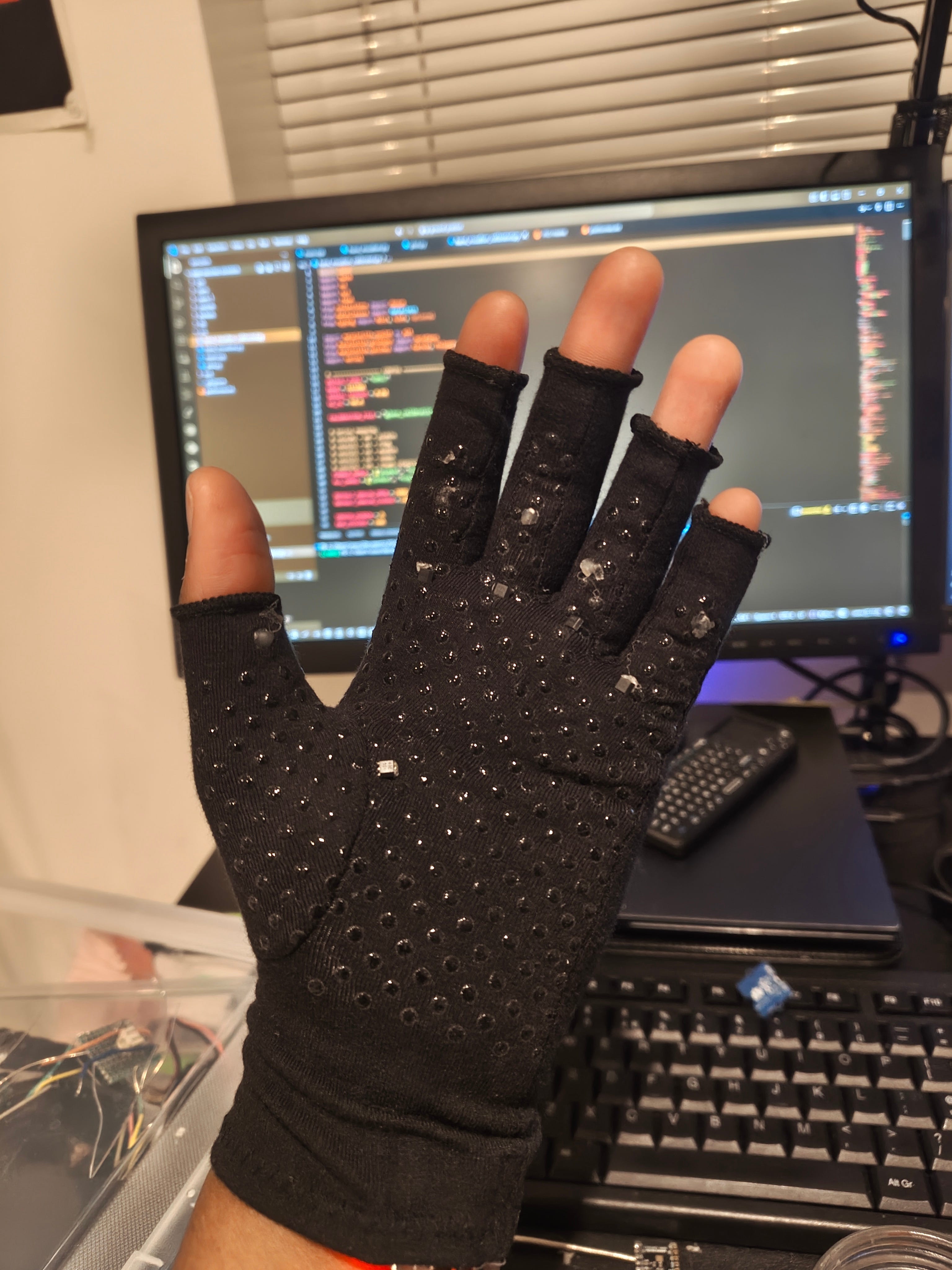
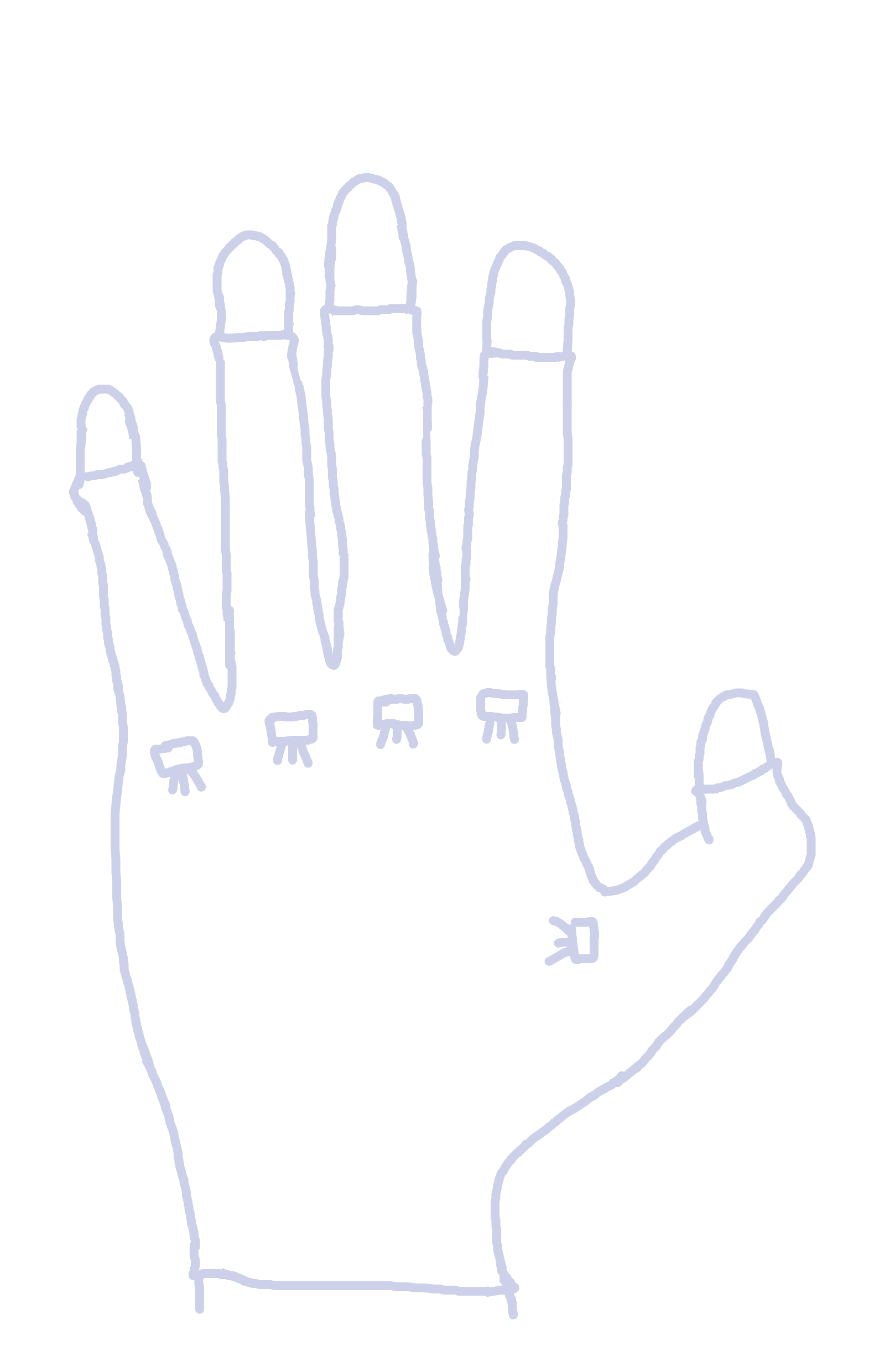
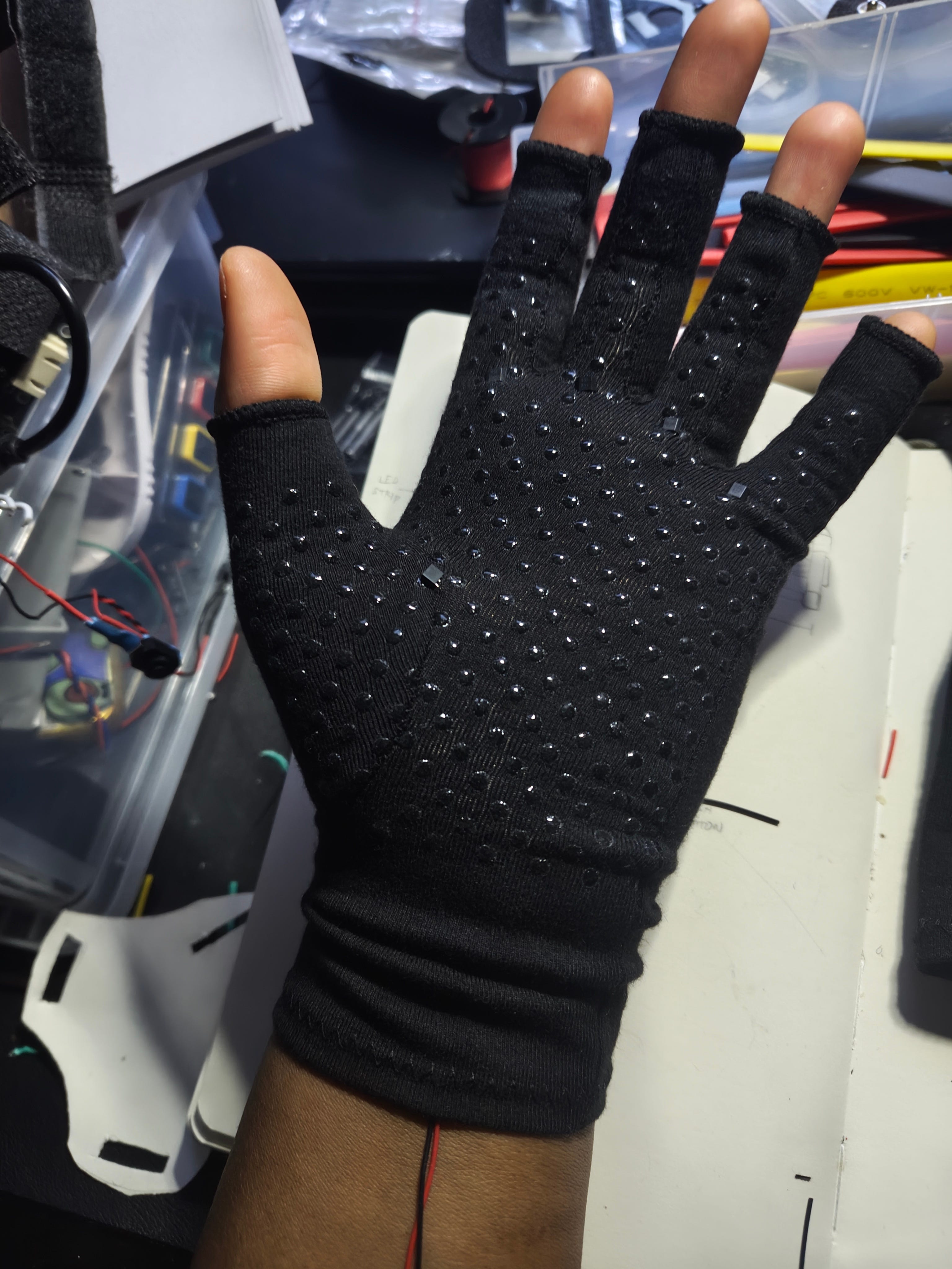
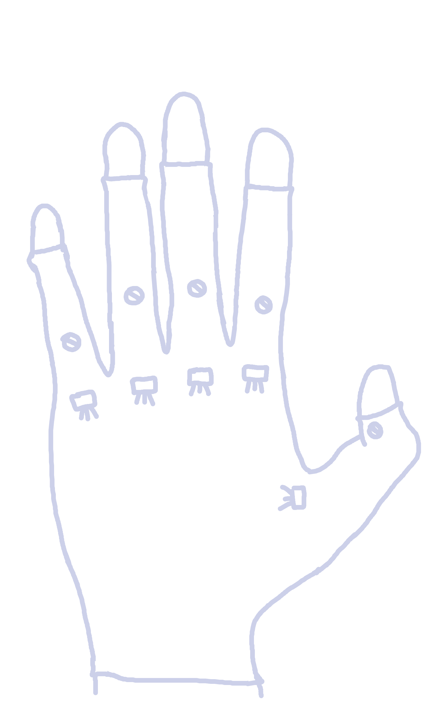
Install the hall effect sensors
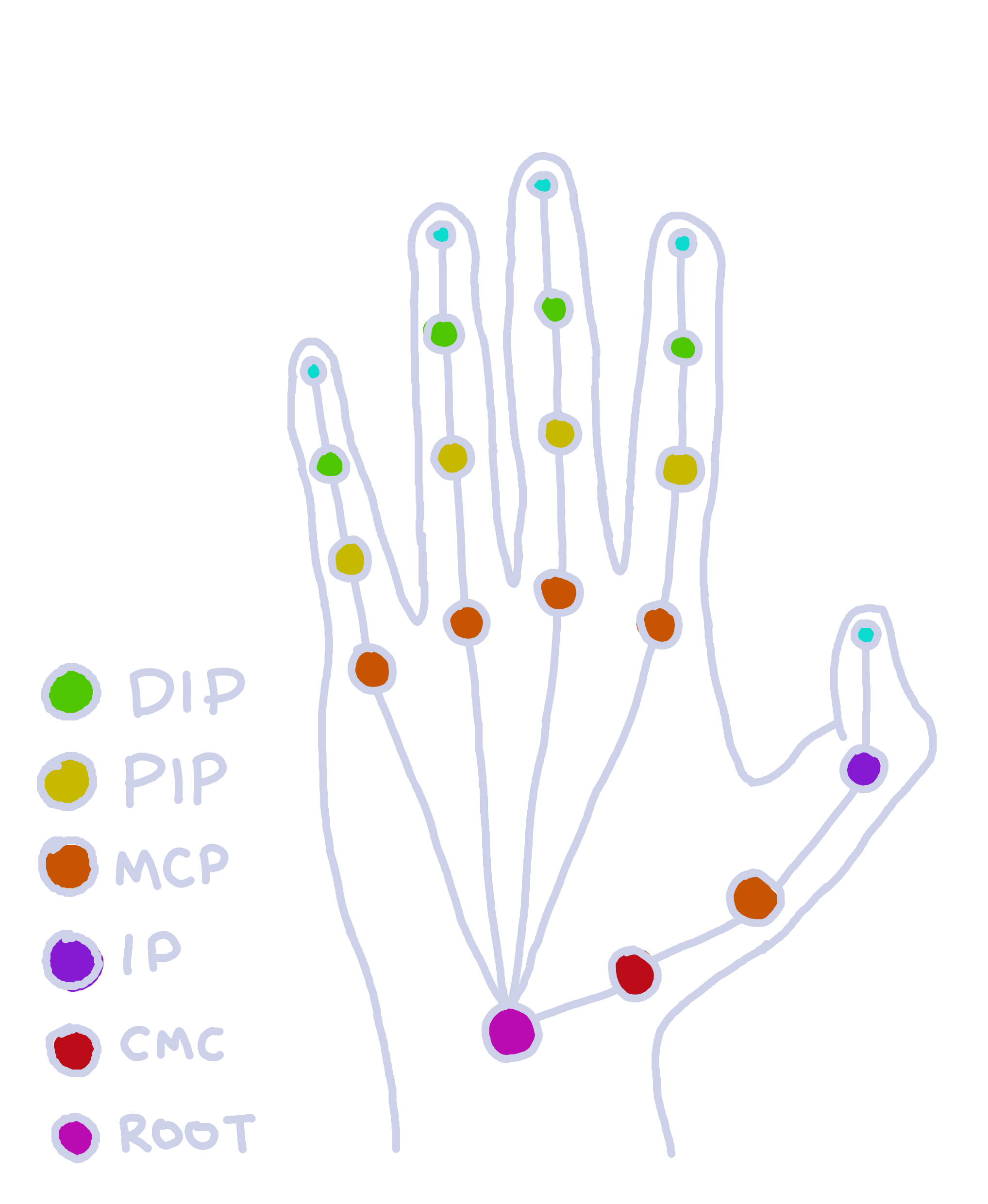
Insert them at the MCP (Metacarpophalangeal) joint of the front of the glove. I recommend you put it on to see if they are in the right position.
The hall effect sensors should be facing up, with their backs on the palm.
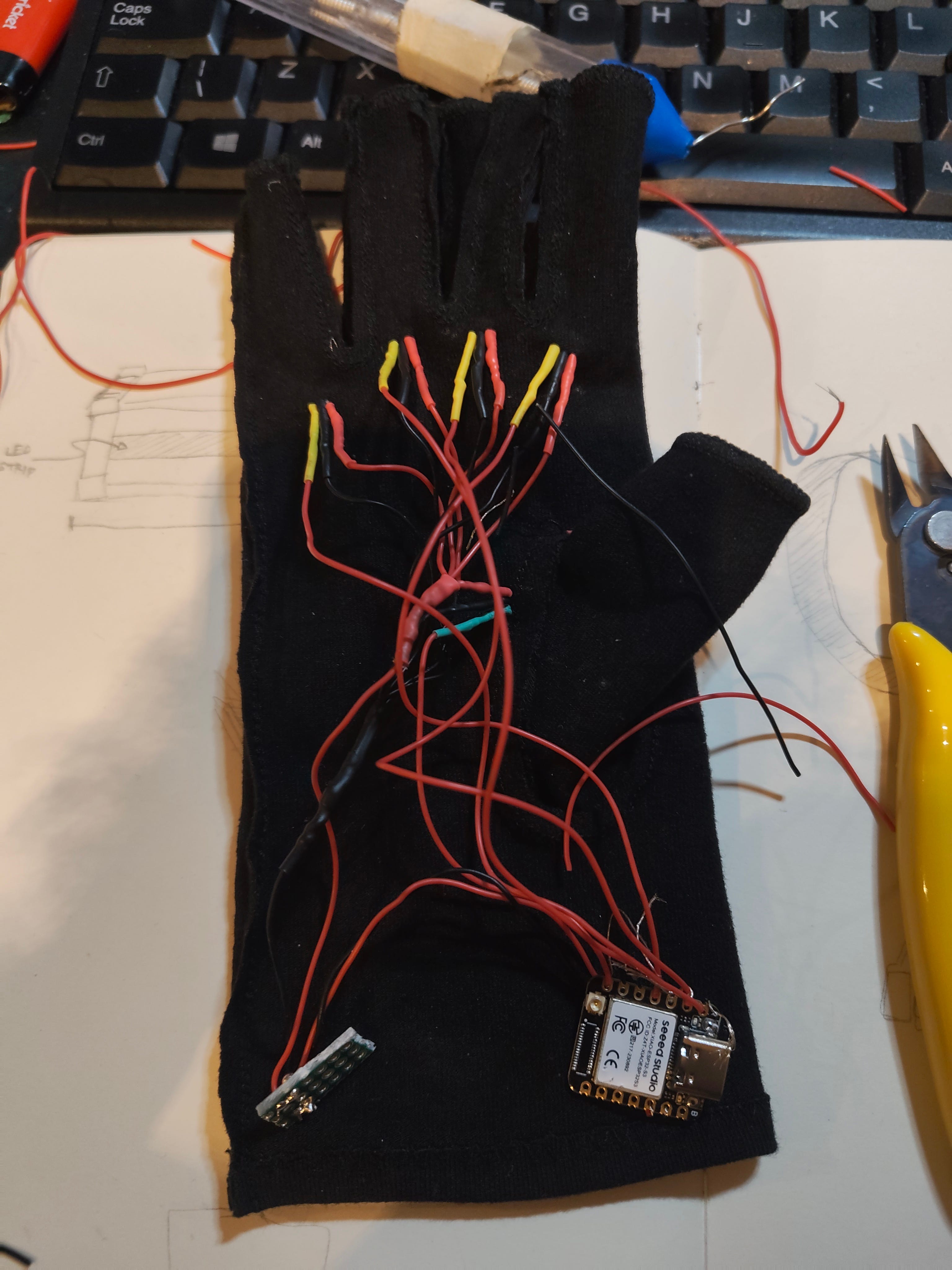
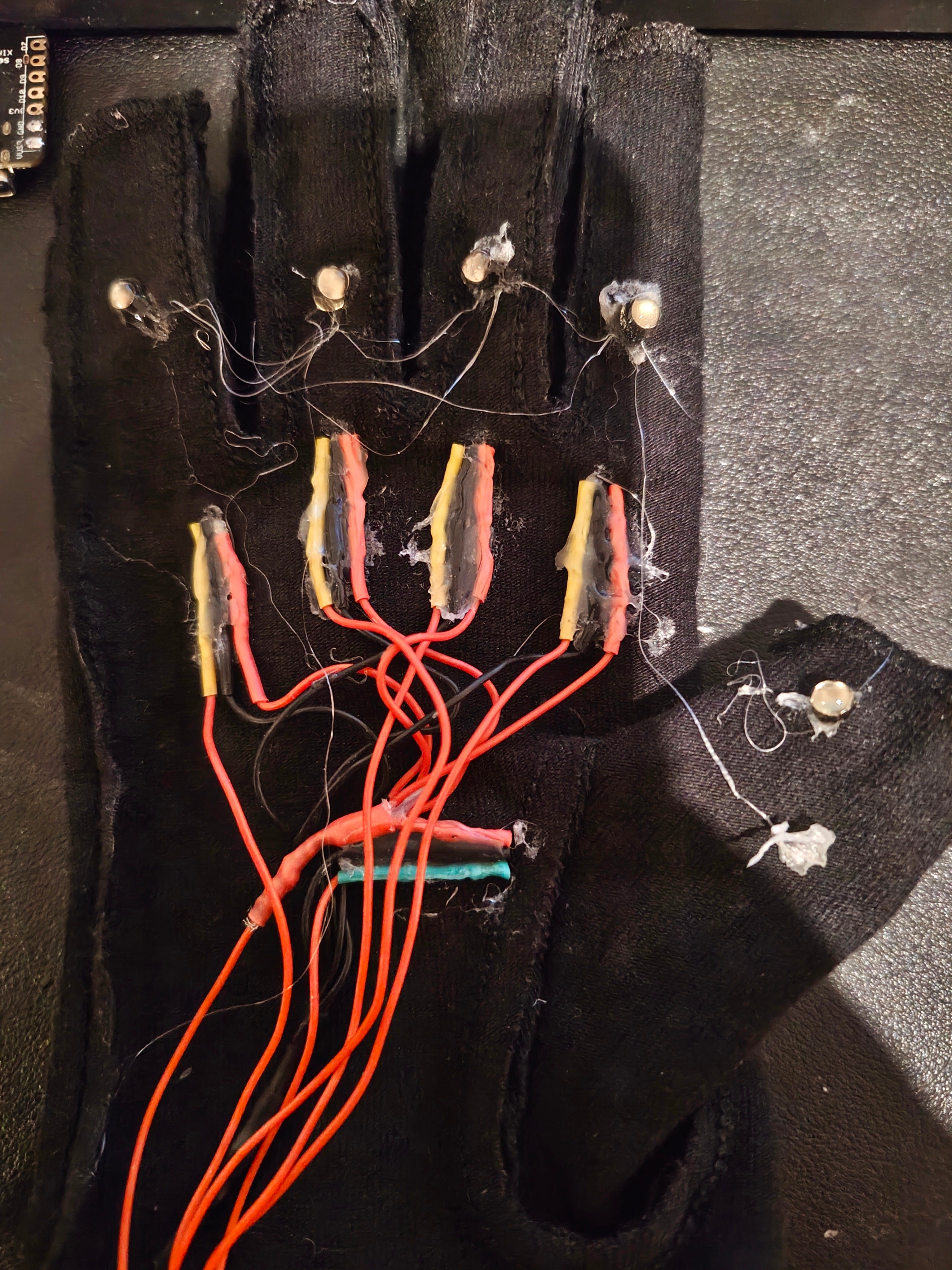
Gently flip the glove inside-out. You want to add wires on the ends of the sensor pins.
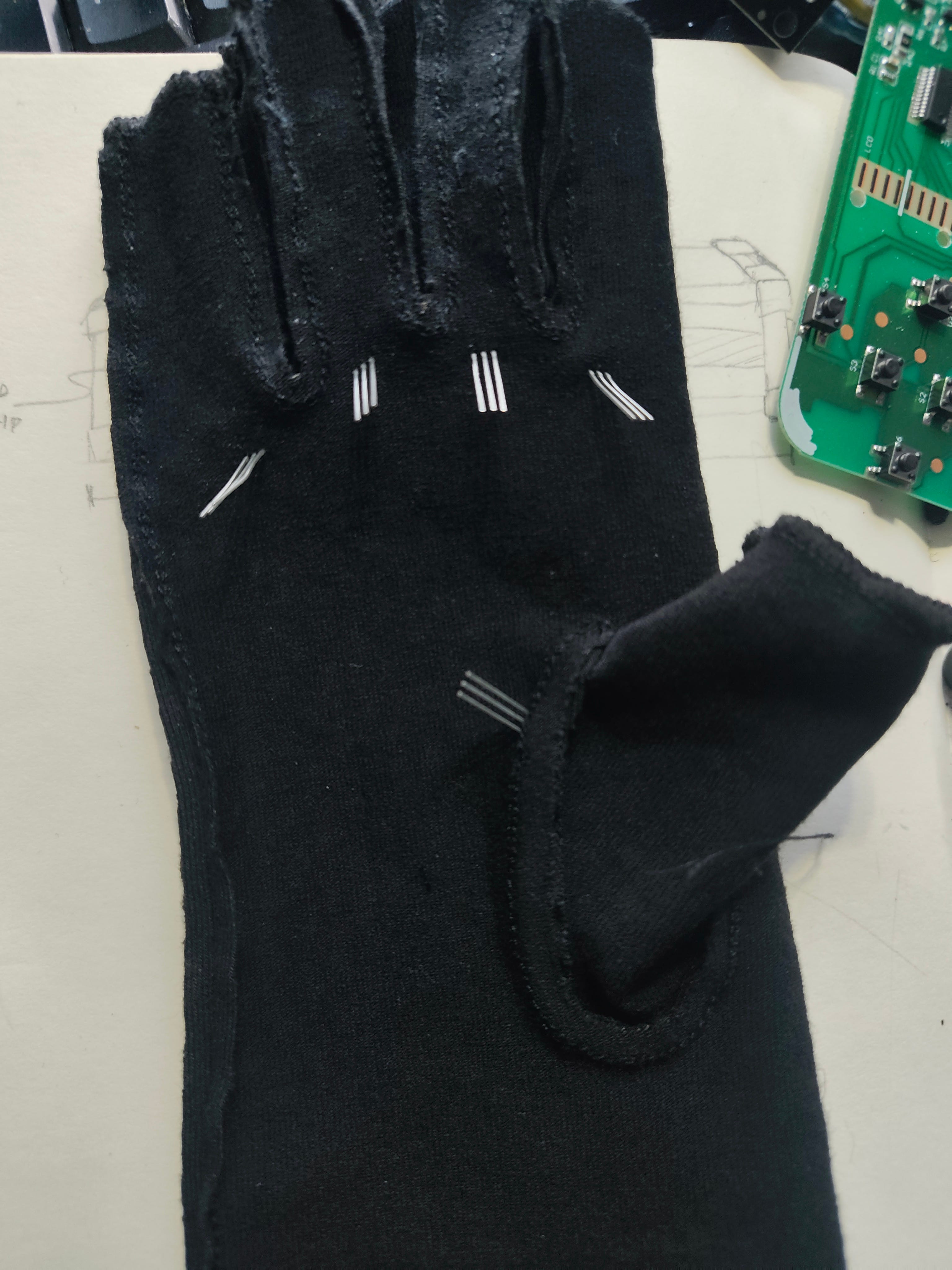
The hall effect sensor has 3 pins: VCC , GND and Analog Output. Solder wires to each of the VCC and GND and repeat for all 5 fingers.
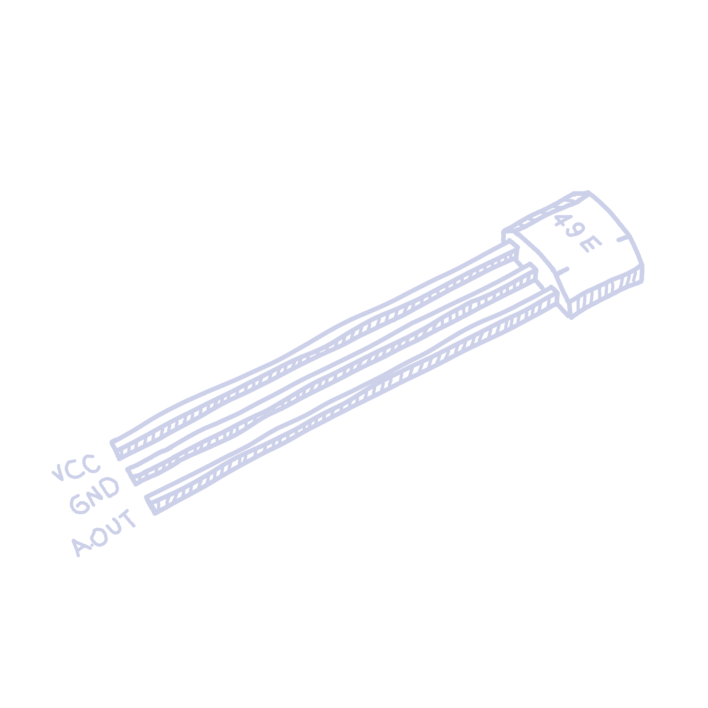
I like to colour code them to make sure I don’t mess it up later (red for VCC, black for GND). We will do the Analog Out pin later. Wrap your wire around each pin, then solder it in place. Finally, add a heat shrink and ensure there is no exposed wire. Its really easy to get a short with so little space to work with, so be careful here.
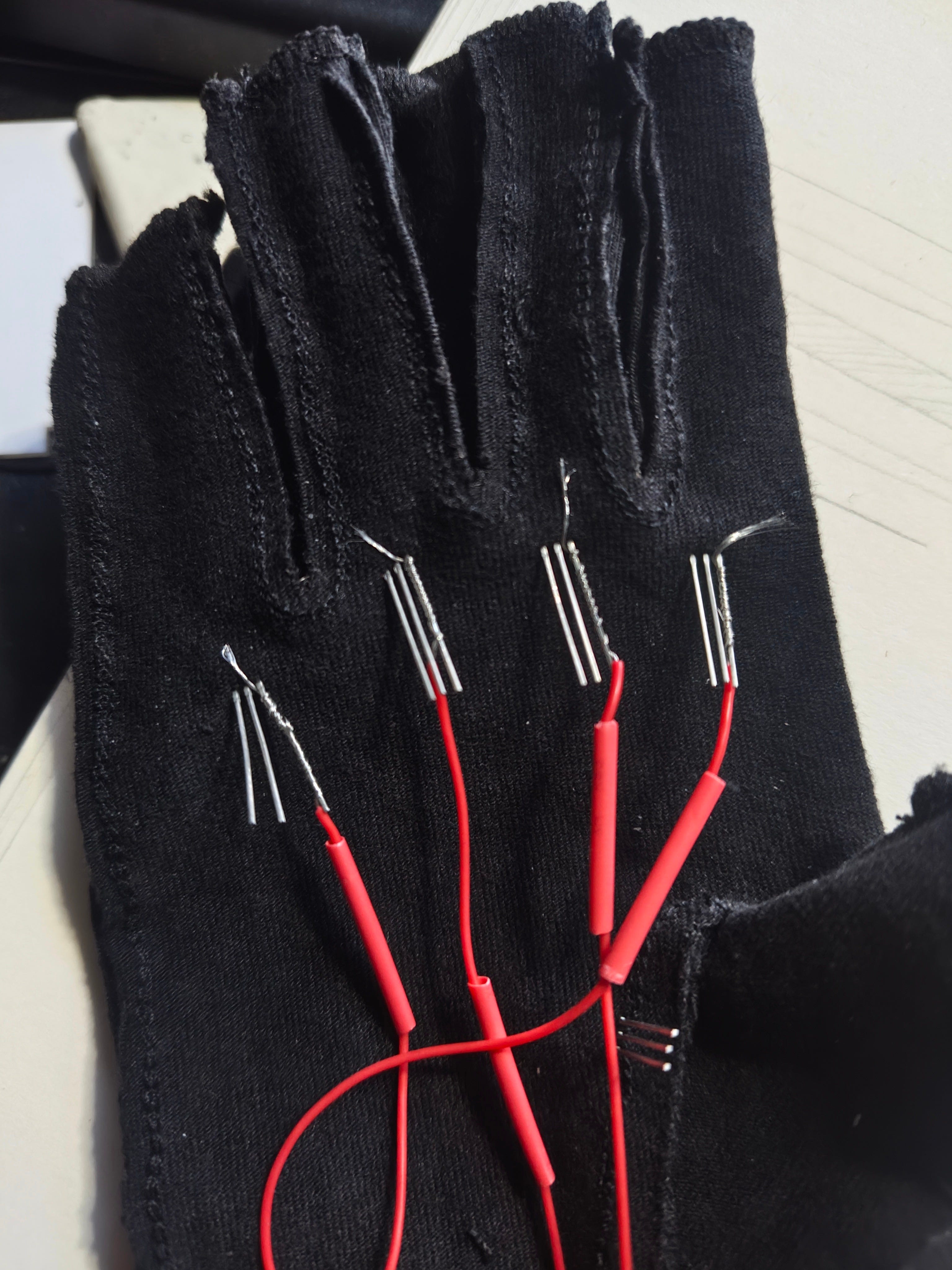
Make the wire relatively long so you have excess. Then heat shrink the wire, ensuring there are no exposed metal contacts.
Since the VCC and GND are all going to the same place, it’ll save a lot of space if they’re connected before they get to the board. Cut all the GND wires but one till they reach about the centre of the palm. The extra one will go to the board. I left the thumb uncut. Strip the cut wires and twist them together. Expose a bit of wire on the uncut wire and wrap the cut wires around it. Now all the wires should be connected to one single wire we will connect to the board. Solder and heat shrink to keep them stable.
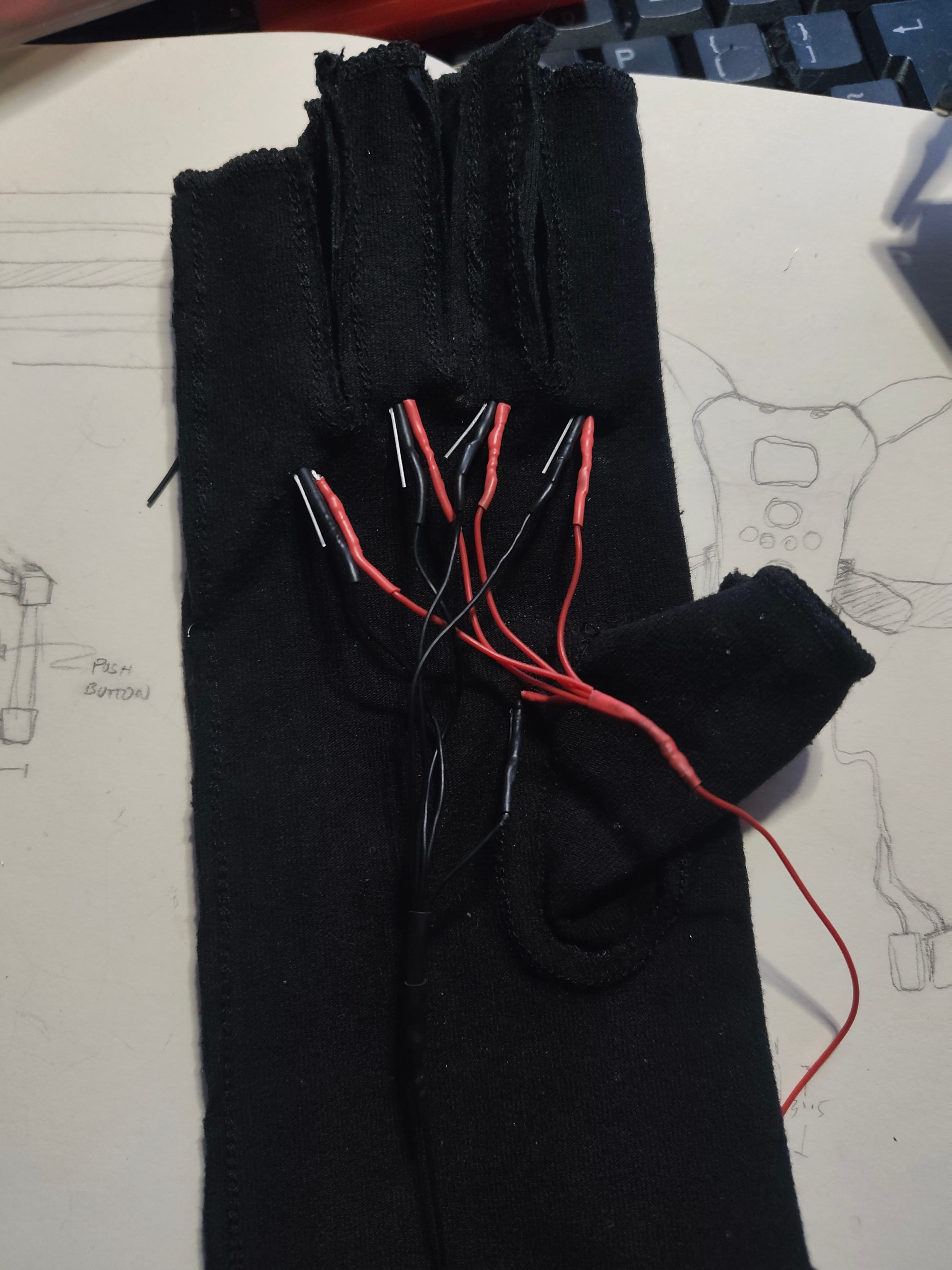
I recommend trying on the glove at every point to ensure it fits comfortably and the wires aren’t too tight/ don’t affect movement. Repeat the same for VCC. You should now have 2 wires coming out of the glove.
Wire up the output pins
Repeat the same thing for the input pins, but do not connect them together. We need those separate to collect their individual values, and we’ll feed this into our esp32-s3. You should now have 7 wires coming out of the glove.
TIP!
Check with a multimeter to ensure there are no shorts (the GND should not be touching the VCC, and the input pins should be touching neither.)
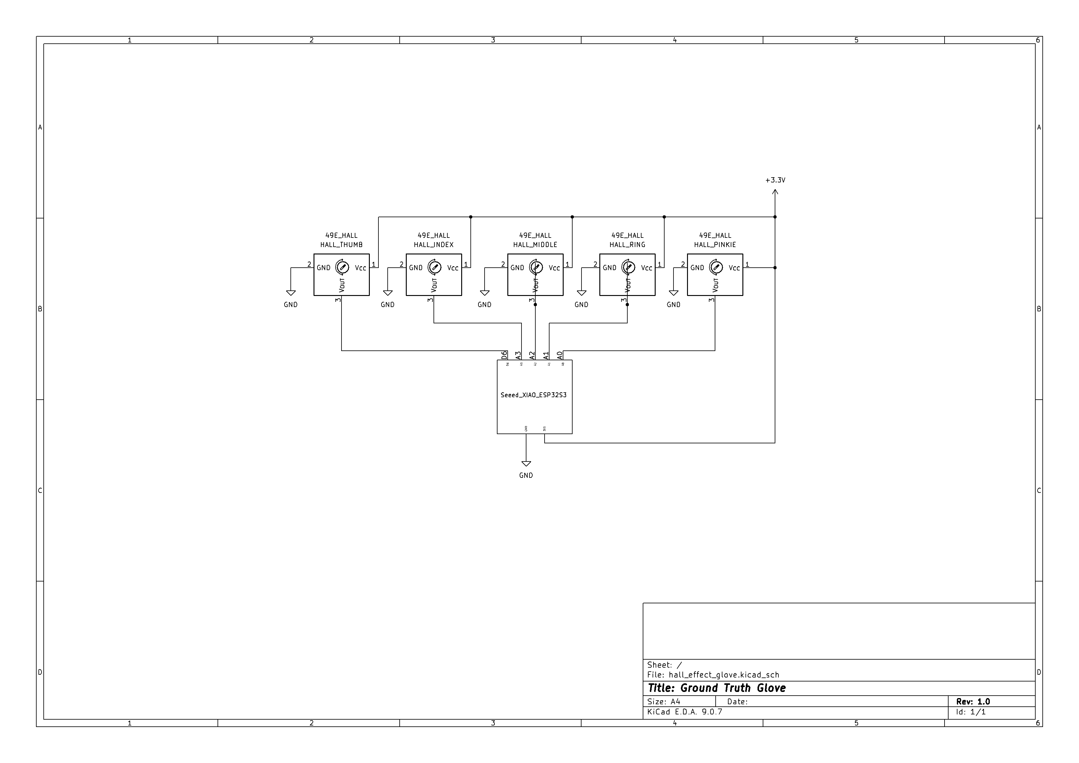
Wiring
Solder the GND and VCC to a very small PCB. We will expose our VCC and GND to this board to allow us to connect more components later. If you don’t plan on adding on the flex sensors, you can wire them straight onto the PCB.
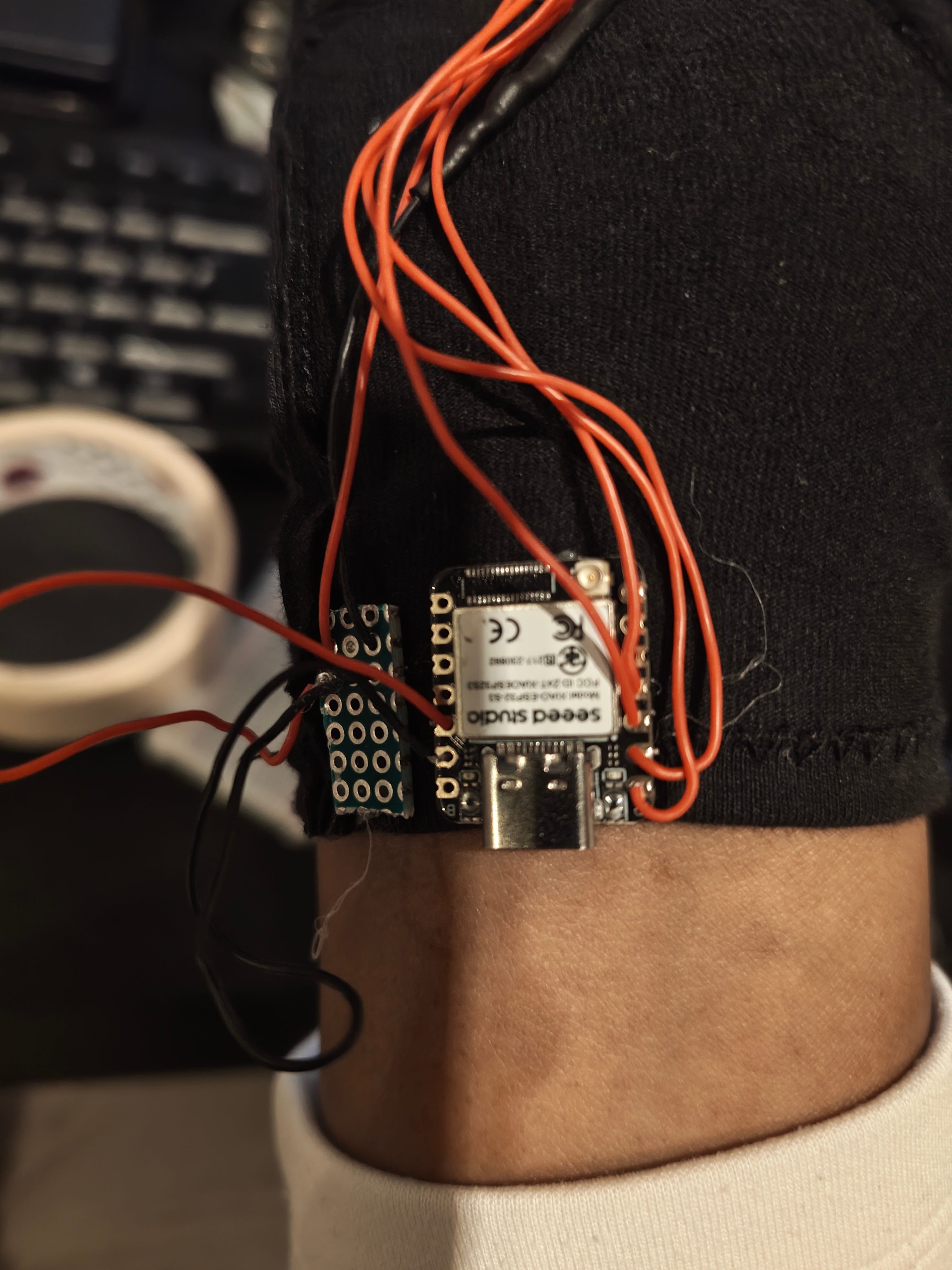
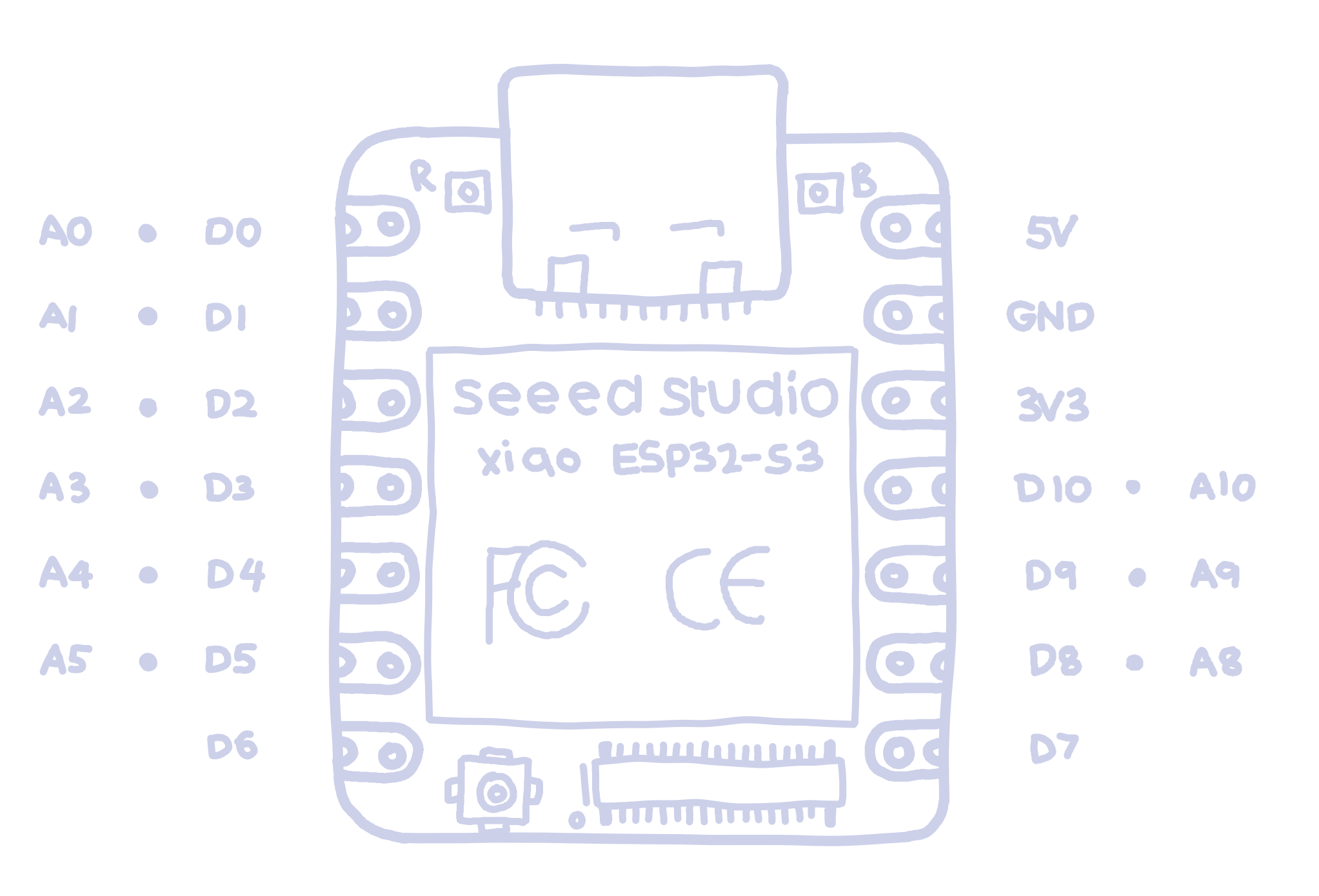
Connect that to the ESP-32. The VCC should go to 3V of the ESP-32 and the GND to GND.
Connect the Output pins:
Pinkie - A0
Ring - A1
Middle - A2
Index - A3
Thumb - D6
NOTE
Pin D6 is a digital pin, which means the values from it will be digital (0 or 1). This is used because I will be adding flex sensors, but there are not enough analog pins on this board. So I have ‘sacrificed’ the thumbs analog capabilities for it. If you don’t plan on adding flex sensors, feel free to change the pins around. Or if you’re using a different board, with more analog pins, change that too. Do whatever you want. Just remember to change the code accordingly.
I hot glued the bottom of the heat shrinks to keep them in place (since the fingers will be moving a lot).
If you’re brave, solder everything to the board directly. I would however recommend testing with a breadboard to ensure your wiring is correct. To do this, wire everything up the same way, but through a breadboard. Then upload the code (shown in The Code section). You should see values being printed in the serial monitor every few milliseconds. If you place a magnet near the sensors, the numbers should go up or down.
Clean up glove
I plan on putting the electronics in the band of my glove, and you should do whatever works the best for yours. I simply hot-glued a piece of cloth over the wires to reduce the stress from wearing the glove on them.
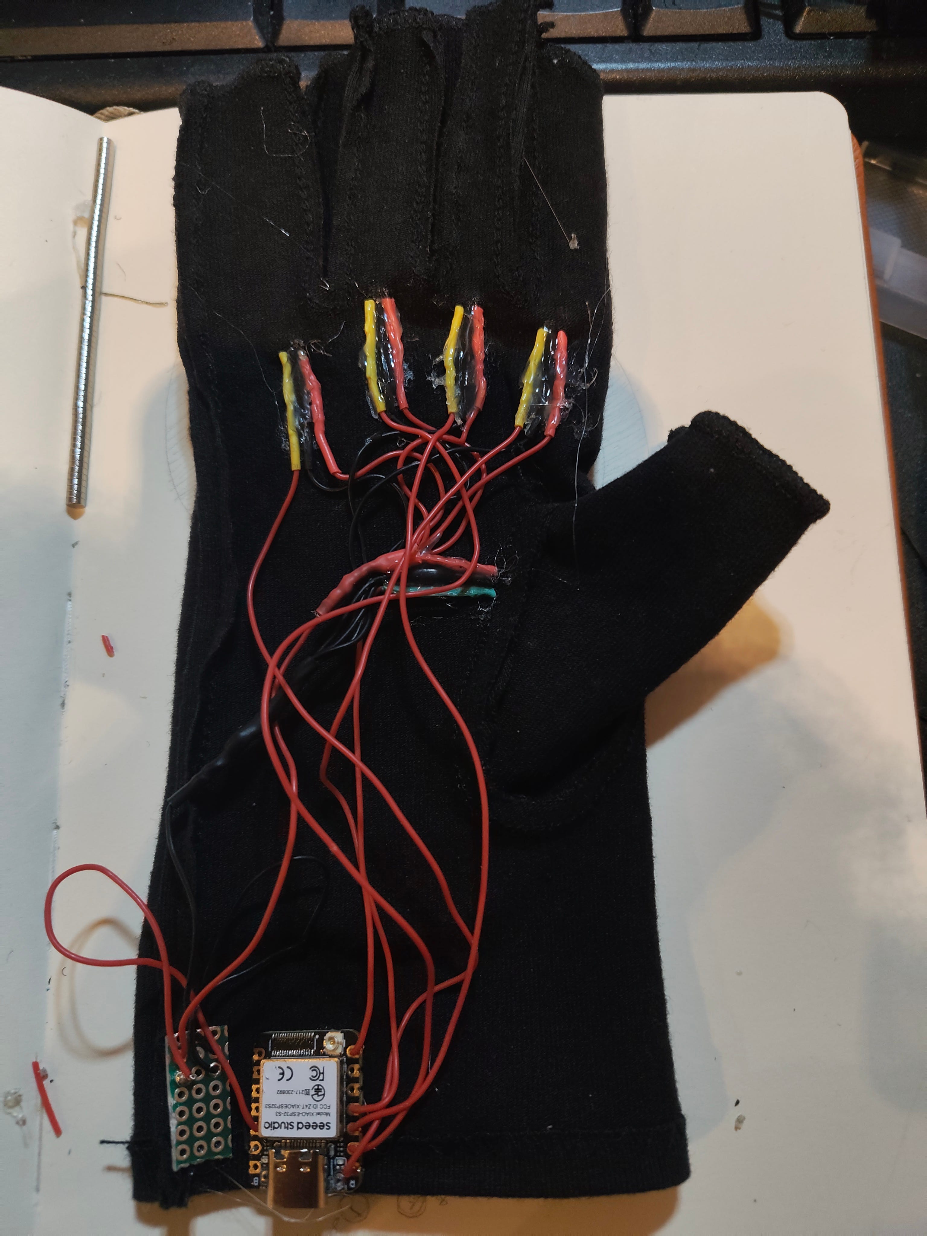
I hot glued the board onto the band of the glove, so that the USB-C port is sticking out.
Add the magnets
I placed magnets around the DIP (Distal Interphalangeal) and PIP (Proximal Interphalangeal) joints, depending on the finger.
I initially used just duct tape to hold them in place, and I recommend wiring the glove to a microcontroller and run plot.py (included in The Code section) to see what points give the best readings on your glove. When you run the code and look at the plotted graph, you should see a clear increase and decrease in the value of the sensor.
Once you are sure about the magnet positioning, you can hot glue them in place.
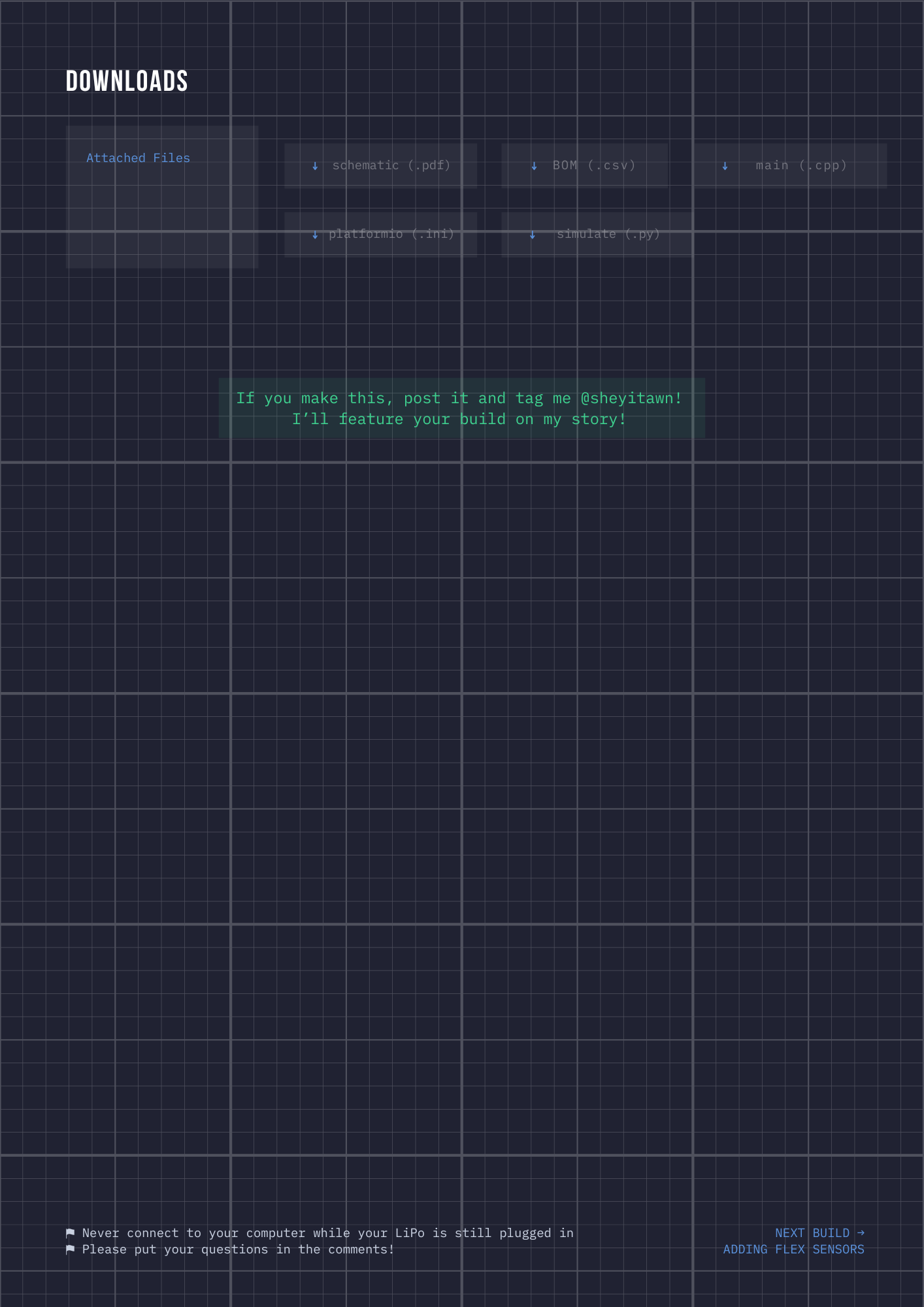
The Code
All the code and files can be found here:
You are free to use any IDE. I have used PlatformIO for this project. Here is my guide to setting up PlatformIO and downloading the files.
You will need to change the COM port in the plot.py. You can see this by checking the bottom of your editor, with the PlatformIO settings.
DEFAULT_PORT = "COM17" # change if neededUpload main.cpp onto your ESP32-S3. Then run plot.py in an new terminal with:
python plot.pyA new plot should open up and you should see a stream of 4 analog values, and 1 digital. If you do not see much movement, you may have to:
adjust the position of your magnets.
change the ANALOG_MIN and ANALOG_MAX: tweak these values to zoom in and out of the graph.
Once you are able to see a reasonable change in each of the fingers, then your magnets are placed correctly.
Now you can try out the hand_visualiser.py. Remember to change the COM port. Run it with:
python hand_visualiser.pyOnce you have this running, press C to calibrate. It will prompt you to open your hand, then close it. This stores your calibration data to glove_calibration.json. You should be able to see a pretty cool visualisation of your finger positions!
Please note that the information in this post is subject to updates to improve correctness and readability. Any issues or improvements? Send me an email at sheyitawn@gmail.com!